Rollbar For The WW2 Jeep
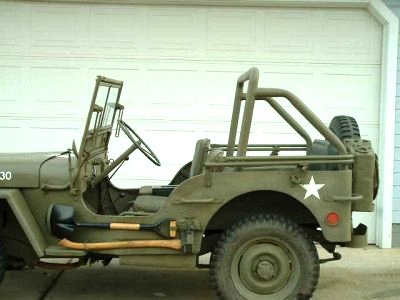
Above. The rollbar pipe is 2″ in diameter. The mounting plate is 5″x 3/8″ flat plate. The height is 29.5″ just under the canvas top, yet not out of proportion with the rest of the jeep if the top is off. A muffler shop useing a mandrel could not bend the top bar as sharp as desired so the designer used weldable 90 degree elbows on them. Some rollbars are created with the big looping bends on the top bar and the designer thought it would not look correct on a WW2 jeep. The Willys MB/Ford GPW jeep are built with a lot of angles, and the designer tried to carry that through the roll bar as well.
Designer’s Comments:
First I feel I must explain the reason for my roll bar. Two weeks before I got my jeep, a local guy was killed on a mountain road in his new 1942 jeep purchase. His new roll bar was sitting in his driveway. My wife said “You’re not driving that thing until it has a roll bar”. My design is more cosmetic than functional. I would probably survive the first roll. The third, fourth, and fifth revolution, I would be history. I know there arw stronger ways to build one, but I’m not into four wheeling. Chico is a collage town and I have added an extra brake light and only venture in there on weekends and evenings.
I also used seat belts out of a 72 Chevelle. The roll bar is not much good if you fly out of the machine.

Above. Front view, looks good clean, almost as if it really belongs there.

Above. Rear view, clearly showing the lines of the rollbar. The angle braces were bent by a local muffler shop. They would not bend a roll bar, (liability) so the designer had to tell them it was a bicycle rack.

Above. Driver side view, this time show how the top bows will work with the rollbar. It’s important to make sure that the rollbar will not interfere with the operation of the top bows. Otherwise you may find that your top is no longer usuable or require modification of the rollbar.

Above. Close-up view of the rollbar joints described above. Notice the relatively sharp angles of the main rollbar.
DISCLAIMER: Design of safety devices and enhancements should ONLY be done by proffessional engineers. The original designer and the author of these web pages accept NO responsibility or liability for YOUR implementation of this design. It is posted here strictly for INFORMATIONAL purposes. Neither the designer nor the author have any CONTROL over YOUR implementation of this device or any other “safety device”. Please use common sense and do not exceed your skills or attempt to do anything you otherwise would not do if a “safety device” were not installed. Be safe!
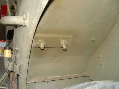
Above. Close-up view of the rollbar details, looking from inside the vehicle out. Notice the mounting plates and the curves of the rollbar, designed in a manner to offer protection to the occupants but allow the toolboxes to continue to function.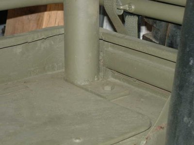
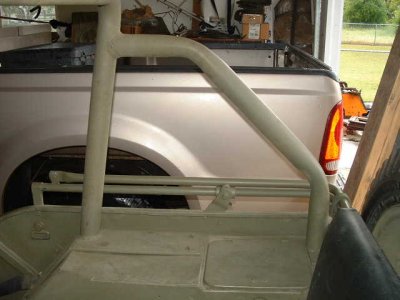
Above. Close-up of the rear mount. There is just barely clearance between rollbar and the toolbox lid. There is only one bolt apparently holding the rear mount to the body, an optional extra bolt could be added by drilling the mount with a bolt opposite the one seen and welding the head in place then weld the rollbar to the mount. Underneath the mount a larger plate should be used to sandwich the body material. This is to help minimize the “punch through” effect on roll over as energy is directed toward the jeep body. The forces will be dissipated as it copes with the different size mount. Note: Not being a structural engineer this is strictly theory on my part.
Above. Close-up of one of the main rollbar mounts. Because this mounting plate is smaller then the one on top (or it could just as well be the other way around), it will minimize the “punch through” effect. This design requires two such mounting plates, this one and an upper mount. An optional, (though more difficult to make) plate would be to make one larger plate (still differing size from the main rollbar plate.)

Above. Interior vehicle shot showing the main rollbar plate. It is approximately 5″ x 23″ x ⅜”” plate (dimensions are approximate-suite to fit) with a bend to fit around the inner fender.
Above. Angled Interior vehicle shot showing the rollbar plates with sizes nominally indicated, suite to fit. Front plate is approximately 5″ x 23″ x ⅜” with a bend to fit around the inner fender and the rear plate is approximately 5″ x 2″ x ⅜”(dimensions are approximate-suite to fit).
DISCLAIMER: Design of safety devices and enhancements should ONLY be done by proffessional engineers. The original designer and the author of these web pages accept NO responsibility or liability for YOUR implementation of this design. It is posted here strictly for INFORMATIONAL purposes. Neither the designer nor the author have any CONTROL over YOUR implementation of this device or any other “safety device”. Please use common sense and do not exceed your skills or attempt to do anything you otherwise would not do if a “safety device” were not installed. Be safe!
 How many would you buy at this price? Well, mine ended up costing me about $650.00. It was shipped from Europe and came with the compressor, mounting brackets, studs, fender box, hose with proper fittings and the double pulley for the crank. Very nice.
 These are the bits I received from the Netherlands. Pretty complete kit.
 The hose is rubber and does not have the cloth cover that Terry’s has.
 Side view. BTW this is a heavy little sucker.
 Straight on view. The four holes is were the single engaging “bolt” is pushed threw. This one is very stiff and requires lube and working it back and forth.
 The other side. Notice that the label is currently painted over. I will attempt to remove the upper layers.
 Rear view of the compressure. There is a plastic or bakelite cup with the word “UP” on the back.
 The repro box that came with my setup. Something is not quite right. Either my Philo jeep body is wrong (good possibility!) or the box is wrong because it doesn’t mate well to the fender location.
 Another view of the box. All in all it is well done. I just have to figure out how to mount it to what I have. It will hold a slew of stuff like the hose (and?).
 Here the box is just sitting on the step. You can see there appears to be some problems. Apparently the step should be 11 11/16 inch long. Mine appeared to be only 11 1/4. At any rate the box does not currently set flush. I will grind off that edge in the bottom right of the picture.
 View of the two new studs installed. Removal of the old. First one was a piece of cake. The second one required me to cut a fine nut in half (not much thread available) and put it on the stud first then the head nut. Came out like a charm using that trick.
 My T1 installed! Well, okay a slight problem. I wasn’t able to fully seat the crankshaft pulley. I will try using an air hammer to put the nut on. Also, I have to figure out what size belt the setup needs. But I am close…very close!