From an article by Captain Howard R. Johnson, Infantry as published in the Infantry Journal, November-December 1940.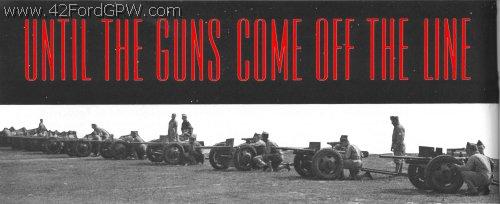 Once you have your jeep restored or completed to your satisfaction the question becomes do you move onto other vehicles or collect other toys for your jeep? Below is an article by Capt. Johnson detailing how to build a replica of an anti-tank gun. No it wasn’t because Capt. Johnson finished his jeep and needed new toys. Actually this was written before most units had every seen or heard of the jeep. The American military was building and preparing for war. After decades of neglect the Army was being re-equipped but “until the guns come the line”, Capt. Johnson and his men needed something to train with. We as collectors can build the AT gun for other reasons and it should get you some interesting looks!
Until our guns come off the line, how are we to train antitank units? This problem confronting every commander of a new antitank outfit has been solved in one unit. Company A, 93d Infantry Battalion (AT), has constructed ?trainer guns? that are proving highly effecttive in training.
And every other AT unit can do the same thing. All it takes is two weeks, a little help from an ordnance machine shop and the exercise of the Yankee ingenuity in every U. S. Army outfit. The whittling and baling-wire-repair tradition in action can produce “weapons” that not only look close enough to the real thing to scare a tanker but also serve to give essential training to gunners. If you don?t believe it, look at the pictures. One of these shows a dozen AT ??guns? manufactured recently at Fort Meade and now in service teaching embryo antitankers the how-and-why of dealing with hostile tanks.
Once you have your jeep restored or completed to your satisfaction the question becomes do you move onto other vehicles or collect other toys for your jeep? Below is an article by Capt. Johnson detailing how to build a replica of an anti-tank gun. No it wasn’t because Capt. Johnson finished his jeep and needed new toys. Actually this was written before most units had every seen or heard of the jeep. The American military was building and preparing for war. After decades of neglect the Army was being re-equipped but “until the guns come the line”, Capt. Johnson and his men needed something to train with. We as collectors can build the AT gun for other reasons and it should get you some interesting looks!
Until our guns come off the line, how are we to train antitank units? This problem confronting every commander of a new antitank outfit has been solved in one unit. Company A, 93d Infantry Battalion (AT), has constructed ?trainer guns? that are proving highly effecttive in training.
And every other AT unit can do the same thing. All it takes is two weeks, a little help from an ordnance machine shop and the exercise of the Yankee ingenuity in every U. S. Army outfit. The whittling and baling-wire-repair tradition in action can produce “weapons” that not only look close enough to the real thing to scare a tanker but also serve to give essential training to gunners. If you don?t believe it, look at the pictures. One of these shows a dozen AT ??guns? manufactured recently at Fort Meade and now in service teaching embryo antitankers the how-and-why of dealing with hostile tanks.
 In order to get the most good from trainer guns, it is desirable that a unit have at least one real 37-mm. gun per company. This allows the men to see, handle, and become familiar with the real thing. Even if they have only a limited familiarity with the 37-mm. gun itself, crews can get real training in elementary and advanced gun drill on the wooden weapon.
Once the squads are thoroughly trained in elementary and advanced gun drill on the trainer gun, they can take up tactical employment beginning with combat principles of the squad and working up to the company. Trainer guns are ideal in combat training if their mobility equals that of the regular gun.
Sandwiched between elementary gun drill and combat training should come laying on still targets and tracking of moving targets. In dealing with the last, training should start at slow speed, using constant ranges, and work up to fast speed and varying ranges.
It is obvious that the benefit derived from this sort of training depends largely on the sight used. It is highly important that the gunner get a picture fairly similar to that obtained when he looks through a regular sight. Hence trainer sights must be constructed with some care.
Squads should be alternated on the one 37?mm. gun available in order to thoroughly learn nomenclature, stripping, assembling, and functioning.
Another training expedient that has proved helpful is the trainer tank. This is a frame, shaped like a tank, constructed of 2 x 4 wood and covered with target cloth. The conning tower is made of beaverboard. The assembly can be easily and quickly installed or removed from the standard half-ton truck. The gun is a piece of salvaged pipe. Such a “tank” lends interest and realism to tracking exercises and combat problems, pending the day we will have real equipment to work with.
From an article by Captain Howard R. Johnson, Infantry as published in the Infantry Journal, November-December 1940.
Squads should be alternated on the one 37mm. gun available in order to thoroughly learn nomenclature, stripping, assembling, and functioning.
Another training expedient that has proved helpful is the trainer tank. This is a frame, shaped like a tank, constructed of 2 x 4 wood and covered with target cloth. The conning tower is made of beaverboard. The assembly can be easily and quickly installed or removed from the standard half-ton truck. The gun is a piece of salvaged pipe. Such a “tank” lends interest and realism to tracking exercises and combat problems, pending the day we will have real equipment to work with.
CONSTRUCTION
The trainer gun is designed to function exactly like the 37mm. gun in so far as practicable with the means and materials available to the average newly-formed unit. Its construction is simple. For the most part, it can be made of the salvaged materials usually found around army posts and cantonments.
Here is a breakdown and descriptive list of the materials used on our trainer gun. In most instances substitutions can be made to fit the materials actually available. The capital letters preceding the item identify it on the photographs.
In order to get the most good from trainer guns, it is desirable that a unit have at least one real 37-mm. gun per company. This allows the men to see, handle, and become familiar with the real thing. Even if they have only a limited familiarity with the 37-mm. gun itself, crews can get real training in elementary and advanced gun drill on the wooden weapon.
Once the squads are thoroughly trained in elementary and advanced gun drill on the trainer gun, they can take up tactical employment beginning with combat principles of the squad and working up to the company. Trainer guns are ideal in combat training if their mobility equals that of the regular gun.
Sandwiched between elementary gun drill and combat training should come laying on still targets and tracking of moving targets. In dealing with the last, training should start at slow speed, using constant ranges, and work up to fast speed and varying ranges.
It is obvious that the benefit derived from this sort of training depends largely on the sight used. It is highly important that the gunner get a picture fairly similar to that obtained when he looks through a regular sight. Hence trainer sights must be constructed with some care.
Squads should be alternated on the one 37?mm. gun available in order to thoroughly learn nomenclature, stripping, assembling, and functioning.
Another training expedient that has proved helpful is the trainer tank. This is a frame, shaped like a tank, constructed of 2 x 4 wood and covered with target cloth. The conning tower is made of beaverboard. The assembly can be easily and quickly installed or removed from the standard half-ton truck. The gun is a piece of salvaged pipe. Such a “tank” lends interest and realism to tracking exercises and combat problems, pending the day we will have real equipment to work with.
From an article by Captain Howard R. Johnson, Infantry as published in the Infantry Journal, November-December 1940.
Squads should be alternated on the one 37mm. gun available in order to thoroughly learn nomenclature, stripping, assembling, and functioning.
Another training expedient that has proved helpful is the trainer tank. This is a frame, shaped like a tank, constructed of 2 x 4 wood and covered with target cloth. The conning tower is made of beaverboard. The assembly can be easily and quickly installed or removed from the standard half-ton truck. The gun is a piece of salvaged pipe. Such a “tank” lends interest and realism to tracking exercises and combat problems, pending the day we will have real equipment to work with.
CONSTRUCTION
The trainer gun is designed to function exactly like the 37mm. gun in so far as practicable with the means and materials available to the average newly-formed unit. Its construction is simple. For the most part, it can be made of the salvaged materials usually found around army posts and cantonments.
Here is a breakdown and descriptive list of the materials used on our trainer gun. In most instances substitutions can be made to fit the materials actually available. The capital letters preceding the item identify it on the photographs.
 (A)Tube: Made of 1 ¾-in. drainpipe, 62 ¼-in. long with a 2 ¼-in. flanged collar at the muzzle end. Any pipe approximately this diameter and length will do.
(B) Breechring: Made of a piece of wood, 6x6x26-in. turned on a lathe to approximate the appearance of the rear portion of tube and breechring. This block, joined to the tube (A) by a drive fit, is held in position by a wood screw and carriage bolt. The operating handle is of wood, turned on a lathe, and is fastened to the breechring by a large wood screw.
(C) Sleigh: Made of wood ¾ x 4 ¾ x 42 ¼.
(D) Recoil cylinder housing: Made of wood 4 x 4 x 36, rounded on a lathe to 3-in. diameter and quartered on one side to rest under the flat sleigh.
(E) Wood block, 9 x 9 x 7, which goes under the sleigh and in rear of the recoil cylinder housing. It holds the elevating handle, carriage bolts for shoulder-guard group, and the carriage bolt from the breechring which passes through the top of the breechring and is secured by a nut on the bottom of the block.
From an article by Captain Howard R. Johnson, Infantry as published in the Infantry Journal, November-December 1940.
(A)Tube: Made of 1 ¾-in. drainpipe, 62 ¼-in. long with a 2 ¼-in. flanged collar at the muzzle end. Any pipe approximately this diameter and length will do.
(B) Breechring: Made of a piece of wood, 6x6x26-in. turned on a lathe to approximate the appearance of the rear portion of tube and breechring. This block, joined to the tube (A) by a drive fit, is held in position by a wood screw and carriage bolt. The operating handle is of wood, turned on a lathe, and is fastened to the breechring by a large wood screw.
(C) Sleigh: Made of wood ¾ x 4 ¾ x 42 ¼.
(D) Recoil cylinder housing: Made of wood 4 x 4 x 36, rounded on a lathe to 3-in. diameter and quartered on one side to rest under the flat sleigh.
(E) Wood block, 9 x 9 x 7, which goes under the sleigh and in rear of the recoil cylinder housing. It holds the elevating handle, carriage bolts for shoulder-guard group, and the carriage bolt from the breechring which passes through the top of the breechring and is secured by a nut on the bottom of the block.
From an article by Captain Howard R. Johnson, Infantry as published in the Infantry Journal, November-December 1940.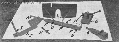 (F) Three yokes: Metal straps of 18-gauge tin molded over the tube, sleigh, and recoil-cylinder housing to hold them together. The yokes are fastened by screws on the bottom side. For additional strength, a large carriage bolt is passed through the tube, sleigh, and recoil housing, and secured on the bottom side by a nut. A metal screw hook receives the free-eye end of the turnbuckle which is used as a travel lock.
(G) Upper Platform: A wooden block, 4 x 9 x 13, center-bored to receive the 34-in. pintle pin of the trunnion fork. It also holds the traversing handle which is secured to it by wood screws. Below the traversing handle on the rear side of the block is secured a turnbuckle whose free end engages on the hook underneath the wooden block described in (E). The block is also bored to receive a &frac1/4;-inch pin which is attached to the block by a chain. This pin passes through a hole in the carriage and holds the gun rigidly in the lateral position while in travel.
(H) Trunnion fork and pin tle: Constructed of ½-in. steel by the ordnance shop. The base of the fork is 5 inches wide and the prongs are 6 ¾ inches long. The prongs are drilled with ¾-in. holes to receive a ¾-in. trunnion pin which passes through drilled holes in the tube and holds it in place on the trunnion fork. Each end of the trunnion pin is drilled to receive the cotter key.
The pintle is a ¾-in. round steel pin, 10 ½ inches long, and is screwed in a drilled ¾-in. hole in the bottom of the fork and then welded. The bottom of the pintle is drilled to receive the cotter key. The fork is secured to the wooden upper gun platform by screws passing through the drilled holes in the base of the fork. This arrangement causes the fork and wooden platform to move in unison when the gun is traversed.
(I) Shoulder-gtiard assembly: Made of wood and 18-gauge tin. The wooden arm is 1 x 5 x 29 shaped as shown in the photograph. The metal shoulder-guard is 11 x 20. All twelve pieces are clamped together and holes punched on a drillpress. The shoulder-guard assembly is attached to the wooden block by means of two carriage bolts secured by nuts.
(J) Sight bracket: A piece of ¼-in. steel constructed by the ordnance machine shop. The shaft is 14 ¾ inches long by 1 ½ inches wide. The bracket is machined to receive the M1917 sight and is welded to the arm.
From an article by Captain Howard R. Johnson, Infantry as published in the Infantry Journal, November-December 1940.
(F) Three yokes: Metal straps of 18-gauge tin molded over the tube, sleigh, and recoil-cylinder housing to hold them together. The yokes are fastened by screws on the bottom side. For additional strength, a large carriage bolt is passed through the tube, sleigh, and recoil housing, and secured on the bottom side by a nut. A metal screw hook receives the free-eye end of the turnbuckle which is used as a travel lock.
(G) Upper Platform: A wooden block, 4 x 9 x 13, center-bored to receive the 34-in. pintle pin of the trunnion fork. It also holds the traversing handle which is secured to it by wood screws. Below the traversing handle on the rear side of the block is secured a turnbuckle whose free end engages on the hook underneath the wooden block described in (E). The block is also bored to receive a &frac1/4;-inch pin which is attached to the block by a chain. This pin passes through a hole in the carriage and holds the gun rigidly in the lateral position while in travel.
(H) Trunnion fork and pin tle: Constructed of ½-in. steel by the ordnance shop. The base of the fork is 5 inches wide and the prongs are 6 ¾ inches long. The prongs are drilled with ¾-in. holes to receive a ¾-in. trunnion pin which passes through drilled holes in the tube and holds it in place on the trunnion fork. Each end of the trunnion pin is drilled to receive the cotter key.
The pintle is a ¾-in. round steel pin, 10 ½ inches long, and is screwed in a drilled ¾-in. hole in the bottom of the fork and then welded. The bottom of the pintle is drilled to receive the cotter key. The fork is secured to the wooden upper gun platform by screws passing through the drilled holes in the base of the fork. This arrangement causes the fork and wooden platform to move in unison when the gun is traversed.
(I) Shoulder-gtiard assembly: Made of wood and 18-gauge tin. The wooden arm is 1 x 5 x 29 shaped as shown in the photograph. The metal shoulder-guard is 11 x 20. All twelve pieces are clamped together and holes punched on a drillpress. The shoulder-guard assembly is attached to the wooden block by means of two carriage bolts secured by nuts.
(J) Sight bracket: A piece of ¼-in. steel constructed by the ordnance machine shop. The shaft is 14 ¾ inches long by 1 ½ inches wide. The bracket is machined to receive the M1917 sight and is welded to the arm.
From an article by Captain Howard R. Johnson, Infantry as published in the Infantry Journal, November-December 1940. (K) Sight, Telescope, M6: If these sights are not available, suitable sights can be made by printing a sight picture on glass discs and placing them in a tin tube. This would necessitate a modifcation of the sight bracket to receive the tube.
(L) Shield: Constructed of 18-gauge tin 20 x 41, the size depending on the carriage used. The shield is reinforced by ¼-in. strapping in the bottom front and top rear. Two braces of ¼-in. steel strips 1 ½ x 17, heated, twisted, and drilled, are riveted to the shield on one end and the upper platform on the other. The shield is secured to the front of the upper platform by four screws through holes drilled in the ¼-in. reinforced strapping.
From an article by Captain Howard R. Johnson, Infantry as published in the Infantry Journal, November-December 1940.
(K) Sight, Telescope, M6: If these sights are not available, suitable sights can be made by printing a sight picture on glass discs and placing them in a tin tube. This would necessitate a modifcation of the sight bracket to receive the tube.
(L) Shield: Constructed of 18-gauge tin 20 x 41, the size depending on the carriage used. The shield is reinforced by ¼-in. strapping in the bottom front and top rear. Two braces of ¼-in. steel strips 1 ½ x 17, heated, twisted, and drilled, are riveted to the shield on one end and the upper platform on the other. The shield is secured to the front of the upper platform by four screws through holes drilled in the ¼-in. reinforced strapping.
From an article by Captain Howard R. Johnson, Infantry as published in the Infantry Journal, November-December 1940.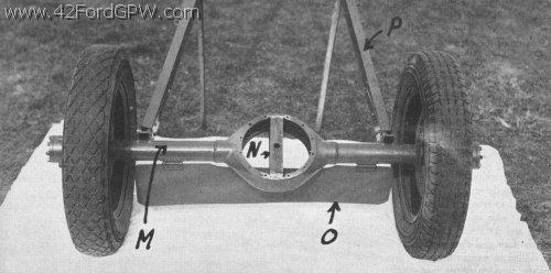 (M) Lower carriage: This is the rear-axle assembly of a salvaged 1934 Dodge ½-ton truck. However, various front axles, Matthews mounts, or other substitutes, will do satisfactory service as running gears.
(N) Lower platform: Two ½-in. steel straps, center-drilled by ¾-in, holes, are welded so that the upper and lower straps are flush with the top and bottom of the differential housing. The pintle pin is seated in these holes and positioned by a cotter key. The traversing locking pin described in (C) is seated in one of these holes.
(0) Apron: Constructed of 18-gauge tin riveted to 3-in. hinges which are in turn welded to the axle. The apron has a 6-inch hook to hold it in the traversing position. The hook is secured into the front face of the shield and its eye is welded onto the apron.
(P) Trails: These are made of 2 x 4 x 8 wood, reinforced on both ends by 18-gauge tin. The trails are secured to the axle by io-in. strap hinges. The strap hinges are bolted to the trails with carriage bolts and are welded to the trails at the lugs formerly used as spring rests
(M) Lower carriage: This is the rear-axle assembly of a salvaged 1934 Dodge ½-ton truck. However, various front axles, Matthews mounts, or other substitutes, will do satisfactory service as running gears.
(N) Lower platform: Two ½-in. steel straps, center-drilled by ¾-in, holes, are welded so that the upper and lower straps are flush with the top and bottom of the differential housing. The pintle pin is seated in these holes and positioned by a cotter key. The traversing locking pin described in (C) is seated in one of these holes.
(0) Apron: Constructed of 18-gauge tin riveted to 3-in. hinges which are in turn welded to the axle. The apron has a 6-inch hook to hold it in the traversing position. The hook is secured into the front face of the shield and its eye is welded onto the apron.
(P) Trails: These are made of 2 x 4 x 8 wood, reinforced on both ends by 18-gauge tin. The trails are secured to the axle by io-in. strap hinges. The strap hinges are bolted to the trails with carriage bolts and are welded to the trails at the lugs formerly used as spring rests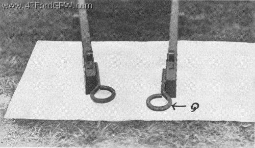 (Q) Lunettes: These are of ¾-in. round iron stock, heat-turned, and welded to a ¼-in. steel plate bolted to the inner surface of the rear end of the trails. Broom or mop handles do duty as rammer staffs and are secured to the trail by a commercial spring-latch and tin holding-clips.
Salvaged brake levers from Renault tanks will serve as elevating and traversing handles.
(Q) Lunettes: These are of ¾-in. round iron stock, heat-turned, and welded to a ¼-in. steel plate bolted to the inner surface of the rear end of the trails. Broom or mop handles do duty as rammer staffs and are secured to the trail by a commercial spring-latch and tin holding-clips.
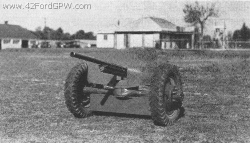
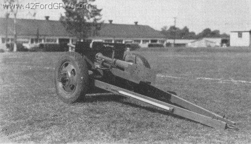
Salvaged brake levers from Renault tanks will serve as elevating and traversing handles. The completed training weapon ready for action.
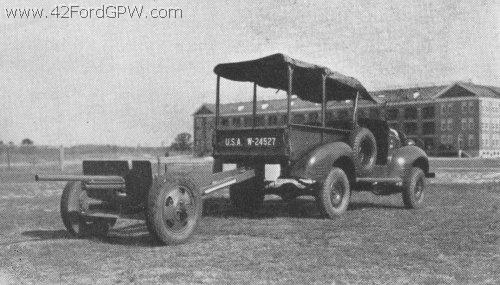 Concept based on an article by Captain Howard R. Johnson, Infantry as published in the Infantry Journal, November-December 1940.
 By now, perhaps you have already read Until The Guns Come Off The Line or part one of this story. Basically one officer dreamed up a solution to fill a desperate training need during those months before the start of World War II for the United States. After offering the article on G503 several of the readers began to coordinate the designing and building of a new more accurate “training” device loosely based on the previously mentioned article.
One of the developers, Mac McCluskey, a machinist by trade, led off with the production of some basic parts. What follows is the ongoing saga of building the M3A1 37mm Anti-Tank Gun (Training) and M4A1 Carriage. The detail is nothing short of amazing.
By now, perhaps you have already read Until The Guns Come Off The Line or part one of this story. Basically one officer dreamed up a solution to fill a desperate training need during those months before the start of World War II for the United States. After offering the article on G503 several of the readers began to coordinate the designing and building of a new more accurate “training” device loosely based on the previously mentioned article.
One of the developers, Mac McCluskey, a machinist by trade, led off with the production of some basic parts. What follows is the ongoing saga of building the M3A1 37mm Anti-Tank Gun (Training) and M4A1 Carriage. The detail is nothing short of amazing.
First up was to obtain a copy of TM 9-1245 Ordnance Maitenance – 37mm Anti-Tank Guns M3 and M3A1 and Carriages M4 and M4A1.
First up was to obtain a copy of TM 9-1245 Ordnance Maitenance – 37mm Anti-Tank Guns M3 and M3A1 and Carriages M4 and M4A1.