Tips- Trouble Shooting – Engine
 It will happen! Your jeep, your baby, your pride and joy will fail to start. It has to be that no account carb again! @#@#@5, dadgumitall! You just replaced it a month ago and already it is all farbed up.
 Chances are there is NOTHING wrong with that carburetor and that should be the LAST thing you check in attempting to diagnose what is wrong with your jeep.
As pictured above you should start with:
Chances are there is NOTHING wrong with that carburetor and that should be the LAST thing you check in attempting to diagnose what is wrong with your jeep.
As pictured above you should start with:
- Sparkplugs
- Battery/Ignition Cables
- Distributor
- Ignition Timing
- Valve Clearance
- Carburetor
Trouble Shooting – Sparkplugs
 Sparkplugs should be handled with extreme care to prevent damage to the porcelain. Before removing the sparkplugs, clean the sparkplug recesses with a small brush or compressed air to keep dirt from entering the engine.
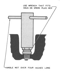 Use a socket wrench of the proper size an apply pressure on the wrench handle exactly parrallel wit the base of the sparkplug. Never use pliersor an adjustable wrench. Sparkplugs with broken porcelain above the metal shell always indicates improper use of tools. If the sparkplug resists turning, do not force it. Turn it back and forth slowly until the threads are free. When extreme tightness is encountered, apply kerosene or fuel oil to the threads and allow it to soak into them. This should free the threads. (Editor’s Note: Please exercise caution don’t pour or spray flammable substances in the engine bay where heat or spark may cause them to ignite. Any “lube juice” of choice can be used, such as, WD-40 or Mystery Oil, etc.)
Sparkplugs can be used for an accuraate diagnosis of engine troubles. Cylinders which are pumping oil excessively will deposit oil on the sparkplug porcelain, where it is easily detected. Engines used for short “start and stop” driving periods will show a black, sooty carbon deposit on the inside porcelain and shell of the sparkplug. Engines used constantly under heavy loads and engines operated when overheated will both produce a brownish film on the porcelain. The latter condition is also indicated by occasional “blistering” and cracking of the porcelain or excessively wide sparkplug gaps. Examine the porcelain insulator for these cracks or blisters and the electrodes for fouling. Replace any sparkplugs that are found to be in this damaged condition.
Use a socket wrench of the proper size an apply pressure on the wrench handle exactly parrallel wit the base of the sparkplug. Never use pliersor an adjustable wrench. Sparkplugs with broken porcelain above the metal shell always indicates improper use of tools. If the sparkplug resists turning, do not force it. Turn it back and forth slowly until the threads are free. When extreme tightness is encountered, apply kerosene or fuel oil to the threads and allow it to soak into them. This should free the threads. (Editor’s Note: Please exercise caution don’t pour or spray flammable substances in the engine bay where heat or spark may cause them to ignite. Any “lube juice” of choice can be used, such as, WD-40 or Mystery Oil, etc.)
Sparkplugs can be used for an accuraate diagnosis of engine troubles. Cylinders which are pumping oil excessively will deposit oil on the sparkplug porcelain, where it is easily detected. Engines used for short “start and stop” driving periods will show a black, sooty carbon deposit on the inside porcelain and shell of the sparkplug. Engines used constantly under heavy loads and engines operated when overheated will both produce a brownish film on the porcelain. The latter condition is also indicated by occasional “blistering” and cracking of the porcelain or excessively wide sparkplug gaps. Examine the porcelain insulator for these cracks or blisters and the electrodes for fouling. Replace any sparkplugs that are found to be in this damaged condition.
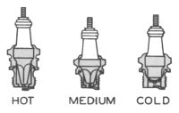 Sparkplugs must allow for correct heat transfer from the combustion chamber to the coolant in the cylinder block. Dirty or damaged sparplug gaskets will hinder this transfer of heat and result in the sparkplug’s running too hot. This may be noticed by blistering or cracking of the porcelain or by the electrodes’ being badly burned after a comparatively short period of operation. If sparkplugs operate too hot after correct gaskets are installed, the engine may be running at higher than normal temperature. The radiator, fan belt, and water pump should be inspected. If these are not at fault, the sparkplugs should be exchanged for ones of cooler operating characteristics as indicated by the number on the sparkplug porcelain. Consult the vehicle specifications for the correct sparkplug number. (Editor’s Note: The correct sparkplugs for the jeep is Firestone F-40, Auto-Lite AN-7, modern numbers include Champion 871 and J8C which can be cross-referenced to other brands/numbers.
To clean sparkplugs fouled with carbon or covered with a brownish-grey powder, it is best to use a sand-blast cleaner of the type furnished by the manufacturer of the sparkplugs. However, never use a sand-blast cleaner on aircraft-type, mica-insulator sparkplugs. When such a cleaner is not available, scrape the carbon off the insulator and electrodes with a small penknife and then clean the sparkplug with solvent or gasoline (Editor’s Note: Use proper caution with anything flammable.) Use compressed air to blow away all traces of the cleaning solution and dirt.
When adjusting the gap between the electrodes, bend only the outside electrode (the one which is attached to the metal shell of the sparkplug). Attempting to adjust by moving the center electrode will crack or break the insulator surrounding it. When adjusting the gap opening, use a round wire feeler gage of the proper size rather than a flat one. The older the
Sparkplugs must allow for correct heat transfer from the combustion chamber to the coolant in the cylinder block. Dirty or damaged sparplug gaskets will hinder this transfer of heat and result in the sparkplug’s running too hot. This may be noticed by blistering or cracking of the porcelain or by the electrodes’ being badly burned after a comparatively short period of operation. If sparkplugs operate too hot after correct gaskets are installed, the engine may be running at higher than normal temperature. The radiator, fan belt, and water pump should be inspected. If these are not at fault, the sparkplugs should be exchanged for ones of cooler operating characteristics as indicated by the number on the sparkplug porcelain. Consult the vehicle specifications for the correct sparkplug number. (Editor’s Note: The correct sparkplugs for the jeep is Firestone F-40, Auto-Lite AN-7, modern numbers include Champion 871 and J8C which can be cross-referenced to other brands/numbers.
To clean sparkplugs fouled with carbon or covered with a brownish-grey powder, it is best to use a sand-blast cleaner of the type furnished by the manufacturer of the sparkplugs. However, never use a sand-blast cleaner on aircraft-type, mica-insulator sparkplugs. When such a cleaner is not available, scrape the carbon off the insulator and electrodes with a small penknife and then clean the sparkplug with solvent or gasoline (Editor’s Note: Use proper caution with anything flammable.) Use compressed air to blow away all traces of the cleaning solution and dirt.
When adjusting the gap between the electrodes, bend only the outside electrode (the one which is attached to the metal shell of the sparkplug). Attempting to adjust by moving the center electrode will crack or break the insulator surrounding it. When adjusting the gap opening, use a round wire feeler gage of the proper size rather than a flat one. The older the sparkplug, the more material will have burned off the electrodes and the more spherical will be the space in which the spark jumps. For this reason a flat feeler gage will sometimes give an incorrect reading. Most sparkplug gap openings will very from 0.020 in. to 0.040 in., depending on the vehicle. (Editor’s Note: The jeep Willys Overland MB and Ford GPW should be gapped at 0.030 in.) The average setting is about 0.025 in.
When installing, be certain that each sparkplug has a single gasket in excellent condition, preferably new. Screw the sparkplug in the hole by hand. (Editors Note: some mechanics suggest apply a high temperature anti-seize material on the sparkplug prior to installation.) When the sparkplug is seated, apply a socket wrench with a handle no longer than 4 in. Finish tightening by turning the socket by hand pressure for an additional one-half to three-quarters of a turn. This will firmly seat the gasket without crushing it. Too much tension on the socket wrench will distort the sparkplug case and vary the gap. Make sure the terminals on the end of the sparkplugs are firmly screwed on, and wipe any grease or moisture off the porcelain insulator.
Trouble Shooting – Battery and Ignition Cables
sparkplug, the more material will have burned off the electrodes and the more spherical will be the space in which the spark jumps. For this reason a flat feeler gage will sometimes give an incorrect reading. Most sparkplug gap openings will very from 0.020 in. to 0.040 in., depending on the vehicle. (Editor’s Note: The jeep Willys Overland MB and Ford GPW should be gapped at 0.030 in.) The average setting is about 0.025 in.
When installing, be certain that each sparkplug has a single gasket in excellent condition, preferably new. Screw the sparkplug in the hole by hand. (Editors Note: some mechanics suggest apply a high temperature anti-seize material on the sparkplug prior to installation.) When the sparkplug is seated, apply a socket wrench with a handle no longer than 4 in. Finish tightening by turning the socket by hand pressure for an additional one-half to three-quarters of a turn. This will firmly seat the gasket without crushing it. Too much tension on the socket wrench will distort the sparkplug case and vary the gap. Make sure the terminals on the end of the sparkplugs are firmly screwed on, and wipe any grease or moisture off the porcelain insulator.
Trouble Shooting – Battery and Ignition Cables
 Battery failure is usually discovered when the cranking motor fails to operate. A simple, positive check of battery condition can be made with a hydrometer. If this test shows that the battery is fully charged, there may be a loose or broken cable. Defects that are not revealed by visual inspection can be localized by making line voltage tests.
Since the acid in the battery electrolyte decomposes as the battery discharges, the weight of the electrolyte gives a direct indication of the state of charge. This weight, or specific graveity, is measured with a hydrometer. To be accurate, the reading must be taken when the bettery is filled to the normal level (⅜ in. above top of plates), but do not test the specific gravity for several hours after adding water. At extremes of temperature it is important to correct hydrometer readings to allow for this variation. The normal standard is 80°F. Add 0.004 for each 10° below standard.
Test each cell with an accurate hydrometer. Each cell of a fully charged battery should read between 1.260 and 1.300. Under normal operating conditions the battery should be removed and recharged if the reading is below 1.225.
Inspect for cracks in the cell covers and containers or for cracked or chipped sealing compound. Slight cracks in sealing compound can be repaired by brushing lightly with a blow-torch flame (Editor’s Note: This may have been and accepted practice in the 40s but a battery generates hydrogen gas and could explode when exposed to flame or sparks.) Cracks in cell covers and container and serious cracking of sealing compound require replacement of the battery.
Battery failure is usually discovered when the cranking motor fails to operate. A simple, positive check of battery condition can be made with a hydrometer. If this test shows that the battery is fully charged, there may be a loose or broken cable. Defects that are not revealed by visual inspection can be localized by making line voltage tests.
Since the acid in the battery electrolyte decomposes as the battery discharges, the weight of the electrolyte gives a direct indication of the state of charge. This weight, or specific graveity, is measured with a hydrometer. To be accurate, the reading must be taken when the bettery is filled to the normal level (⅜ in. above top of plates), but do not test the specific gravity for several hours after adding water. At extremes of temperature it is important to correct hydrometer readings to allow for this variation. The normal standard is 80°F. Add 0.004 for each 10° below standard.
Test each cell with an accurate hydrometer. Each cell of a fully charged battery should read between 1.260 and 1.300. Under normal operating conditions the battery should be removed and recharged if the reading is below 1.225.
Inspect for cracks in the cell covers and containers or for cracked or chipped sealing compound. Slight cracks in sealing compound can be repaired by brushing lightly with a blow-torch flame (Editor’s Note: This may have been and accepted practice in the 40s but a battery generates hydrogen gas and could explode when exposed to flame or sparks.) Cracks in cell covers and container and serious cracking of sealing compound require replacement of the battery.
 If removal is required, first disconnect the ground strap to avoid a short if the wrench strikes the frame while removing the cable to the starting motor. If the bolts and nuts are corroded, hold the terminal with pliers and use a wrench on the nuts. This prevents damage to the battery posts. IF the terminal clamp is not easily released, insert the screwdriver edge of a pair of pliers into the open end of the terminal yoke and twist to release the yoke. Do not hammer the battery post to release the terminal. Do not place a screw driver or other tool under the terminal and pry up on the terminal — this might break the cell cover.
Before installing the replacment battery, make sure the carrier is free from corrosion and has no tools or rocks in it. A tar-base paint can be applied to the carrier to assist in preventing corrosion. Determine the correct location of positive and negative posts before placing the battery in the carrier. The positive post is larger — may also be identified by a “+” or “POS” marking or by red paint on the top surfaces.
When installing the cable terminals, tighten the nuts carefully. Be sure the bolts are long enough to allow each terminal to fit the post correctly. Tighten the hold-down bolts so that the battery cannot shift in the carrier. Take care to avoid unnecessary tension that might crack the case of the battery.
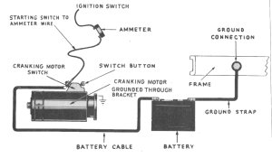
After the terminals have been tightened, check the installation by turning on the headlights with the engine not running. The ammeter should register discharge. IF the ammeter registers charge, remove the battery and install it in the reverse position so that terminals can be connected correctly (Editor’s Note: This presumes that you jeep was wired correctly – if you have just rewired the jeep, suspect the ammeter not the battery).
Special Operating Conditions
When batteries are operated in tropical climates where freezing temperatures are never encountered, the full-charge specific gravity is reduced to the value between 1.210 and 1.225 by dilution with water. Under these circumstances, a tag should be attached to the battery to show the full-charge specific gravity.
Battery capacity is greatly reduced by low temperatures. At 0°F the battery has only 40 percent of the cranking power it has at 80°F. Special care must be taken to keep batteries fully charged, but do not attempt to adjust specific gravity to values above 1.300. At temperatures below -20°F, batteries must be heated during periods of operation and stand-by.
If removal is required, first disconnect the ground strap to avoid a short if the wrench strikes the frame while removing the cable to the starting motor. If the bolts and nuts are corroded, hold the terminal with pliers and use a wrench on the nuts. This prevents damage to the battery posts. IF the terminal clamp is not easily released, insert the screwdriver edge of a pair of pliers into the open end of the terminal yoke and twist to release the yoke. Do not hammer the battery post to release the terminal. Do not place a screw driver or other tool under the terminal and pry up on the terminal — this might break the cell cover.
Before installing the replacment battery, make sure the carrier is free from corrosion and has no tools or rocks in it. A tar-base paint can be applied to the carrier to assist in preventing corrosion. Determine the correct location of positive and negative posts before placing the battery in the carrier. The positive post is larger — may also be identified by a “+” or “POS” marking or by red paint on the top surfaces.
When installing the cable terminals, tighten the nuts carefully. Be sure the bolts are long enough to allow each terminal to fit the post correctly. Tighten the hold-down bolts so that the battery cannot shift in the carrier. Take care to avoid unnecessary tension that might crack the case of the battery.
After the terminals have been tightened, check the installation by turning on the headlights with the engine not running. The ammeter should register discharge. IF the ammeter registers charge, remove the battery and install it in the reverse position so that terminals can be connected correctly (Editor’s Note: This presumes that you jeep was wired correctly – if you have just rewired the jeep, suspect the ammeter not the battery).
Special Operating Conditions
When batteries are operated in tropical climates where freezing temperatures are never encountered, the full-charge specific gravity is reduced to the value between 1.210 and 1.225 by dilution with water. Under these circumstances, a tag should be attached to the battery to show the full-charge specific gravity.
Battery capacity is greatly reduced by low temperatures. At 0°F the battery has only 40 percent of the cranking power it has at 80°F. Special care must be taken to keep batteries fully charged, but do not attempt to adjust specific gravity to values above 1.300. At temperatures below -20°F, batteries must be heated during periods of operation and stand-by.
Trouble Shooting – Battery and Ignition Cables
Battery Cables
Examine the terminals and battery posts for signs of corrosion. Be certain that the nuts turn freely on the bolts and that the bolts are free in the terminal yokes. Remove the bolts and examine them for corrosion and damaged threads. Use ammonia and water or soda (baking soda from a mess hall will do) and water to remvoe corrosion. Be careful to avoid spilling any cleaning solution into the cells; it will destroy the electrolyte. In the absence of these solutions, use a stiff-bristle or wire brush. Replace any terminals corroded; be sure to use terminals of the proper size. If new terminals are soldered on the old cables, make certain that the old cable fits tightly into the new terminal and that the solder is applied with sufficient heat so that it is thoroughly worked through the strands inside the terminal.
Inspect the cables for worn insulation and broken strands of wire a the terminals and the points where the cables pass through openings in the frame. The insulation can be taped if replacements are not available.
Disconnect the battery ground strap where it is connected to the frame, engine or transmission. Clean all surfaces of contact with a knife or file. Replace, making sure the bolt and nut fastens the ground strap or cable securely to the part that holds it. Use new lock washers.
If new terminals are soldered on the old cables, make certain that the old cable fits tightly into the new terminal and that the solder is applied with sufficient heat so that it is thoroughly worked through the strands inside the terminal.
Inspect the cables for worn insulation and broken strands of wire a the terminals and the points where the cables pass through openings in the frame. The insulation can be taped if replacements are not available.
Disconnect the battery ground strap where it is connected to the frame, engine or transmission. Clean all surfaces of contact with a knife or file. Replace, making sure the bolt and nut fastens the ground strap or cable securely to the part that holds it. Use new lock washers.
Trouble Shooting – Battery and Ignition Cables
Line-Voltage Test
Excessive resistance caused by poor terminal connections or defective insulation will result in inadequate voltage at the cranking motor. An abnormal drop in voltage can be detected with a low-reading voltmeter. Make these four tests: A. One prod of voltmeter on grounded battery terminal and the other on vehicle frame. B. One prod on ungrounded battery terminal andthe other on cranking-motor switch stud C. One prod on cranking-motor housing and the other on vehicle frame D. One prod on battery post and the other on cable terminal. For each test, operate the cranking motor with the ignition off. If the voltmeter reading is more than 1/10 volt, there is excessive resistance. For (A), clean or replace the ground strap; for (B), clean or replace the cranking-motor cable; for (C), check the cranking-motor mountings and clean the contact surfaces on the switch; and for (D), remove terminal, scrape clean, replace, and tighten the bolts securely.
Trouble Shooting – Battery and Ignition Cables
High Voltage Cables
Examine thse wires for any signs of frayed or damaged insulation, particularly where they enter a conduit or holder. Examine the terminal ends of the wires for corroded or loose ends. Replace when such conditions are found.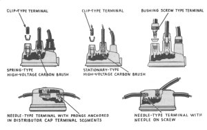
Trouble Shooting – Distributor

Cap
Remove the distributor cap without removing the high-voltage cables. Insepct the inside and outside for cracks and carbon runners. These carbon runners are caused by the high-voltage spark’s jumping and burning the material of which the cap is made. Moisture inside the distributor cap is usually responsible. If cracks of carbon or runners are found, replace the distributor cap. Emergency repairs may be effected by scraping out the carbon runner with a knife or sharp tool.Trouble Shooting – Distributor
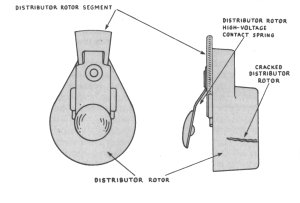 Rotor
Remove the rotor by pulling it straight off the shaft. Inspect for cracks and carbon runners as in the cap. Make sure the spring that maintains contact with the distributor cap is in good condition. If any cracks or carbon runners are present, of if the spring is corroded or weak, replace the rotor with a new one. The replacement must be the same size and type as the old rotor.
Rotor
Remove the rotor by pulling it straight off the shaft. Inspect for cracks and carbon runners as in the cap. Make sure the spring that maintains contact with the distributor cap is in good condition. If any cracks or carbon runners are present, of if the spring is corroded or weak, replace the rotor with a new one. The replacement must be the same size and type as the old rotor.
Trouble Shooting – Distributor
Condenser
See that the condenser is tight in the mounting bracket and that the pigtail is free of bare spots and frayed edges. Be certain the pigtail is firmly attached to the binding post and does not contact any moving parts of the distributor.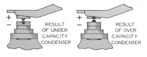
Breaker Points
If a faulty condensor is suspected, the breaker points will usually give an indication of the condenser’s condition. If the points are burned a deep blue or purple color and are covered with a scale, the condenser is shorted. If the points are excessively pitted, with a deep cavity on one surface and a corresponding built-up portion on the other surface (as illustrated above), the condenser is likely to be either under or over capacity. A vehicle will not run properly with a defective condenser, and replacment must be made. If a regular condenser is unavailable, any condenser may be used for an emergency. The radio noise-suppression condensers found on most vehicles will work satisfactorily until the proper condenser can be obtained.Condenser Tests
Several field-expedient tests may be made to determine the condition of a condenser. A test may be made for a shorted condenser with 110-volt alternating current and an ordinary light blub. Connect the test light as shown above. If the light glows, the condenser is shorted and must be replaced. To check on the capacity of the condenser, strike the condenser pigtail lightly with the test prod; after a few seconds, bend the pigtail until the terminal touches the can of the condenser. A light spark should be noticed, acompanied by a snapping sound.
Another method is to place the condenser on the engine of a vehicle which is idling and then bend the pigtail close to the terminal of one of the sparkplugs. Allow the pigtail to contact for only a second; then remove the condenser, being careful to avoid contact with the metal terminal of the condenser. After a few seconds, bend the pigtail until the terminal touches the can of the condenser; this should produce a slight spark, accompanied by the characterisc snapping sound. Occasionally the condenser may not be charged properly on the first try; a second attempt should always be made before condemning any condenser.
To test the condenser without removing it from the distributor, crank the engine until the fiber rubbing block of the points in the distributor is midway between two lobes of the cam. Turn the vehicle ignition switch on and snap the contact points open and closed by hand; at the same time observe the contacts for evidence of flash. No arcing across the points will indicate a grounded condenser. A slight, barely noticeable flash will indicate a normal condenser. A considerable arc or flash across the points will indicate an open-circuited condenser. In either case when the test shows the condeser to be defective, the unit should be replaced.
A test may be made for a shorted condenser with 110-volt alternating current and an ordinary light blub. Connect the test light as shown above. If the light glows, the condenser is shorted and must be replaced. To check on the capacity of the condenser, strike the condenser pigtail lightly with the test prod; after a few seconds, bend the pigtail until the terminal touches the can of the condenser. A light spark should be noticed, acompanied by a snapping sound.
Another method is to place the condenser on the engine of a vehicle which is idling and then bend the pigtail close to the terminal of one of the sparkplugs. Allow the pigtail to contact for only a second; then remove the condenser, being careful to avoid contact with the metal terminal of the condenser. After a few seconds, bend the pigtail until the terminal touches the can of the condenser; this should produce a slight spark, accompanied by the characterisc snapping sound. Occasionally the condenser may not be charged properly on the first try; a second attempt should always be made before condemning any condenser.
To test the condenser without removing it from the distributor, crank the engine until the fiber rubbing block of the points in the distributor is midway between two lobes of the cam. Turn the vehicle ignition switch on and snap the contact points open and closed by hand; at the same time observe the contacts for evidence of flash. No arcing across the points will indicate a grounded condenser. A slight, barely noticeable flash will indicate a normal condenser. A considerable arc or flash across the points will indicate an open-circuited condenser. In either case when the test shows the condeser to be defective, the unit should be replaced.
Trouble Shooting – Distributor
Contact Breaker Points
Separate the breaker points and inspect the contact surfaces. Clean with a fine-cut point file if necessary, but be certain to remove all filings with a clean rag before using. When no file is available, use the sanded surface of a match box, a knife, or a sharp screwdriver blade. Make certain that the contact surfaces are striking squarely and evenly. If the faces of the contact points are not alined perfectly they cannot carry all the current necessary for good coil operation. To aline the contact surfaces properly, bend the stationary point arm or bracket. Never bend the movable arm; bending may weaken the arm and allow it to become bent and misalined in operation. Never grasp the point assembly so that any portion of the pliers or tool will touch the contact surface. Check the action of the movable arm on its pivot. It should move freely by hand against the spring pressure, and when released it shoudl snap back into position. If sluggishness is noted in its operation during this test, the arm should be removed from the pivot and inspected for solidified grease or burrs obstructing its movement. Clean thoroughly and apply a msall amount of petrolatum or light chassis grease before replacing the arm on the pivot. To adjust the contact-point opening, crank the engine until the fiber rubbing block of the contact points is resting on the highest portion of any one of the cam lobes. With a flat feeler gage inserted between the points, adjust the stationary point until a slight drag can be felt when working the gage back and forth between the surfaces. Select the proper thickness of gage after consulting the vehicle specifications. The gap will normally be between 0.015 and 0.020 in., the average gap being about 0.018 in. One type of stationary point has the contact surface mounted on an arm which is securely fastened to the base plate of the distributor. The arm can be adjusted by loosening the locking screw and moving the adjusting screw (a cam head screw) until the desired opening is reached. Another type has the contact surface mounted on a machine screw which is threaded into a plate attached to the base plate of the distributor. To adjust this type, merely loosen the lock nut on the screw shank and turn the screw so the stationary contact moves nearer to or farther from the moveable contact. Be sure to tighten the lock nut securely after the corret gap opening is set, and always recheck the opening to be certain that the point has not been moved in locking the assembly. After the assembly is locked, check the point opening for all the other lobes of the cam to make certain the cam itself is not worn. Any variation of point-gap opening beyond 0.002 in. indicates a defective cam.
Trouble Shooting – Distributor
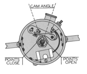
Cam – Angle Test
If the proper test equipment is available, the distributor should be removed and installed on a cam-angle testing machine. This machine accurately measures the degree of angular rotation in which the contact surfaces remain closed. Vehicle specifications include this angle, and in cases where the point-gap opening and the amount of cam angle differ, the cam angle should be accepted as being correct.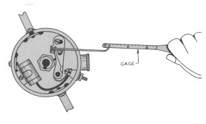 When inspection indicates that contact point replacement is necessary, use identical equipment. Always replace both contact points. In attaching the condenser leads and the movable breaker point spring to the binding post, take care that no part touches a movable portion of the distributor.
Trouble Shooting – Ignition Timing
Determining Firing Order
 The firing order of an engine is usually indicated by numbers embossed on the cylinder head, exhaust manifold, or valve covers. If it is not given, it can be determined by the following method. First remove all the sparkplugs. Then crank the engine by hand and observe when the no. 1 cylinder expels air. Note which cylinder is next to expel air; it will be the one that is next in the firing order. Proceed until all cylinders have been included. An easy way to do this is to fit paper plugs loosely in the sparkplug holes. When the engine is cranked by hand, the force of air on each compression stroke will force the paper plugs out of the sparkplug holes in the order of firing.
Locating Top Dead Center
 Crank the engine until the no. 1 cylinder is on top dead center of the compression stroke. This center can be determined by cranking the engine until a pressure is felt at the no. 1 sparkplug hole. Continue cranking slowly until the pressure ceases. On the flywheel of some engines there is either a steel ball or an etched scribe mark with will appear in the inspection hole of the flywheel housing just before the piston reaches top dead center of the compression stroke. On other engines, this timing mark may be found on the crankshaft pulley on the front of the engine.
Installing Sparkplug Cables
When top dead center of the no. 1 cylinder is located, remove the distributor cap. The rotor should be directly under, or near, one of the high-voltage electrodes on the inside of the cap. Connect the cable from the no. 1 sparkplug to the hole in the distributor cap which correspondes with this electrode. Connect the wires from the other sparkplugs, in their firing order, to the distributor cap, proceeding around the cap in the direction of the rotation of the rotor. To determine this direction without cranking the engine, apply a twisting pressure to the rotor. The direction in which the rotor can be turned against spring pressure is the direction of rotation. Connect the cable from the high-voltage outlet of the coil to the center hole in the distributor cap.Intial Timing
If the distributor has a manual advance, set it at 0. Be sure that the pointer is exactly in line with the mark on the flywheel or crankshaft pulley. Set the timing as follows: Engine Not Running. With the piston of the no. 1 cylinder on top dead center (timing marks alined), the points should be just opening. Loosen the distributor clamp and turn the housing in the direction of rotation of the distributor rotor until the points are closed. Turn on the ignition switch and hold the end of the high-tension cable that enters the distributor cap from the coil a distance of about 1/4 in. from a ground. Turn the distributor in the opposite direction to that of rotation of the distributor rotor until a spark jumps the gap from the high-tension cable to the ground. At this time the points are just opening. Clamp the distributor in this position. Turn ignition off. Engine Running. Replace the distributor cap. Attach one lead of a neon timing light to the no. 1 sparkplug without disconnecting the high-tension cable. Connect the other lead from the timing light to a convenient ground. Start the engine and run at idling speed. Direct the beam of light on the timing mark on the flywheel or crankshaft pulley. Timing light flashes will make the timing marking appear stationary. It should be directly under the pointer. If it is not in this position, the timing should be adjusted until it is. To advance the timing, rotate the distributor housing in the opposite direction from the rotation of the rotor. To retard the timing, rotate the distributor housing in the same direction as the rotation of the rotor. When the timing mark and the pointer are properly alined, clamp the distributor housing. If an ignition timing light is not available, a length of high-tension cable can be used. Place one end against the no. 1 sparkplug cable at the point where that cable comes out of the distributor. Hold the other end of the cable about 3/8 in. from the moving portion of the flywheel or crankshaft pulley. The spark jumping to ground will give much the same effect as a timing light.Other Timing Faults
If the distributor does not rotate when the engine is cranked, first check to see that it is firmly fastened all the way down in the mounting hole. If it is properly fastened and still does not rotate, inspect for a stripped distributor gear or oil-pump gear. It is also also advisable to inspect the cam-shaft gear. (Editors’s Note: It is unusual but possible to insert the tang crooked and “miss” the mate on the oil pump. Try reinstalling.) Occasionally the distributor is blamed for timing trouble which is caused by a worn or loose timing chain. This trouble can be detected by an explosion which occurs during the intake or exhaust stroke and causes a popping noise in either the carburetor air horn or the exhaust pipe. To rememedy this condition, remove the timing gear housing and replace or tighten the chain.Trouble Shooting – Valve Clearance
Valve Cover Gasket
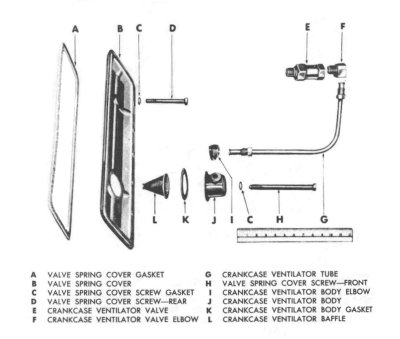 Remove front valve spring cover bolt. Remove crankcase ventilator tube at ventilator valve, and remove tube and cap. Remove rear valve spring cover bolt, and slide valve spring cover forward, up, and out over the fuel pump. Discard gasket. (Editor’s Note: You may want to remove the driver’s side fender/disconnect wiring to facilitate access to the valve area of the engine.)
Valve Tappet Adjustment
 Adjust the self-locking tappet screws while they are cold (or warm) to 0.014 inch. Set tappet screws, starting with No. 1 cylinder on compression stroke at top center, then adjust valves in cylinder firing order, turing the crankshaft one-half turn for each cylinder. NOTE: The valve tappets will then be on the heel of the cam. After adjusting, replace valve spring cover.
Valve Cover Gasket Installation
Clean cover and gasket seat on cylinder block. Cement cork gasket to cover. Position cover on cylinder block by sliding it to the rear over the fuel pump. Install cover rear screw and copper gasket, but do not tighten. Install cover front screw and copper gasket, with ventilator cap, baffle and gasket. Connect ventilator tube to valve, and tighten both cover screws evenly. (Editor’s Note: Use caution when tightening the cover screws. If they do not have a should you could crack the block by over-tightening. This was a problem on some of the GPW blocks.)Trouble Shooting – Carburetor
Failure of the engine to operate is rarely caused by carburetor defects. If it is determined that the carburetor is responsible (that is, the ignition system is working properly and fuel is reaching the carburetor), the carburetor may be clogged or the float level may be improper. The only adjustments the second and third echelons can make on the carburetor are adjustments of the idling speed, the idling mixture, the choke control mechanism, and the accelator pump seasonal adjustment. Improver adjustment should not prevent engine operation, but proper adjustment is necessary for maximum operating efficiency.Connections
Look for leaks at the fuel-line connections. If any leakage cannot be stopped by drawing up the union nut, there maybe a split tube or a poor seat in the union. A damaged flare should be cut off and a new flare made with a flaring tool. Packing with a string may serve as a temporary repair. If the fuel contains a dye, a fuel leak may be indicated by an accumulation of the dye. But it should be remembered that he porous metal used for some castings sometimes permits a small amount of seepage, and an accumulation of dye may be due to this rather than a fuel leak. Leakage may be caused by a split adapter, in which case temporary repair can be made by soldering (Editor’s Note: Use caution when attempting to solder anything used in the fuel system. The parts should be cleaned of all fuel residue before attempting to solder. If you do not already know how to solder, just procure new parts!)Fuel Bowl
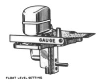
Fuel seeping out around the fuel-bowl cover indicates a loose cover, a damaged gasket or casting, or a defective float valve. Slight seepage is probably due to a loose cover. Extensive seepage is likely to be caused by a defective float valve. (Editor’s Note: The “defective float valve” could simply be the result of contaminated fuel – dirt/rust, etc.)- Remove the fuel-bowl cover to examine the float. If the float contains fuel, causing it to lose bouyancy, determine where the fuel entered the float and drill a small hole (1/8 in.) at this point. Drain the fuel from the float, and patch the hole with a light drop of solder. (Editor’s Note: See comment above about soldering. Today it practical just to obtain a new float in a carb rebuild kit.)
- If the float needle valve and seat show indications of wear, replace them with new parts and new gaskets. From the specifications of the carburetor, adjust the carburetor, determine the correct float level, and set the float by bending the float support arm. Hold the float in the closed position and blow into the fuel-line adapter. No air should pass through the valve. (Editor’s Note: For MB/GPWs set the float with a gage or 3/8 in.)
- Examine the gasket. Replace it if there are any breaks or hardened sections. Be sure the new gasket does not obstruct any apertures in the housings. Draw down the cover screws evenly.