Tips from Army Motors
There is a wealth of information available in the original WW2 Army Motors published by the Technical Service Division, Holabird Quartermaster Motor Base, Baltimore, MD There’s really no trick to adjusting it if you’ll take care of first things first. Jeep Steering Title
As often as not, the simpler units on trucks are more misunderstood than the complicated ones. For instance, you won’t have to snoop around a shop long where steering-gear adjustments on the 1/4-ton jeep (Ford GPW or Willys MB) are under way before you find a mechanic pretty much in the dark about the adjustments he’s making.

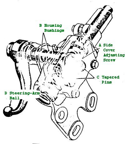
 Before starting your adjustments on the ball thrust bearings on the cam you have to relieve the assembly of all load. Disconnect the steering gear connecting rod from the steering arm, loosen the instrument panel bracket and steering-gear frame bolts to allow the assembly to align itself. Then loosen the housing-side adjusting screw (Fig. 2 A) to free the pins in the groove. Remove or add shims under the housing cover (the shims are in .002′, .003′. and .0lO’ thickness) so that you get a barely perceptible drag on the steering wheel — yet you should be able to turn the wheel freely with thumb and forefinger lightly gripping the rim. The shims can be clipped so they will slip over the shaft, for removal or replacement.
With this shaft properly adjusted, forget it — and start concentrating on the adjustment of the lever-shaft assembly.
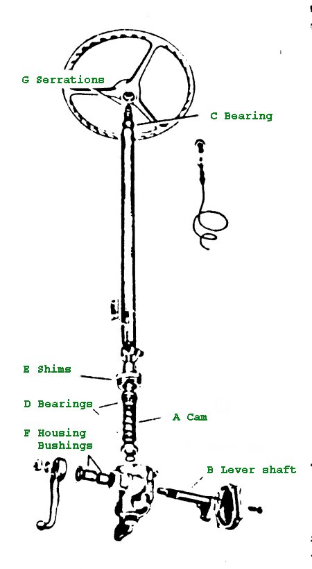
The lever shaft turns in two housing bushings ( F in Fig. 1; B in Fig. 2). If these bushings have been worn or beaten out until they no longer hold the shaft in alignment, further adjustment is time wasted. It’s a good idea to have somebody turn the steering wheel back and forth while you hold the end of the shaft (with the con rod still attached) and check side movement of the shaft in the housing. Unless the fit is really sloppy, you, can’t feel the play by merely moving the shaft with your hand.
Before starting your adjustments on the ball thrust bearings on the cam you have to relieve the assembly of all load. Disconnect the steering gear connecting rod from the steering arm, loosen the instrument panel bracket and steering-gear frame bolts to allow the assembly to align itself. Then loosen the housing-side adjusting screw (Fig. 2 A) to free the pins in the groove. Remove or add shims under the housing cover (the shims are in .002′, .003′. and .0lO’ thickness) so that you get a barely perceptible drag on the steering wheel — yet you should be able to turn the wheel freely with thumb and forefinger lightly gripping the rim. The shims can be clipped so they will slip over the shaft, for removal or replacement.
With this shaft properly adjusted, forget it — and start concentrating on the adjustment of the lever-shaft assembly.
The lever shaft turns in two housing bushings ( F in Fig. 1; B in Fig. 2). If these bushings have been worn or beaten out until they no longer hold the shaft in alignment, further adjustment is time wasted. It’s a good idea to have somebody turn the steering wheel back and forth while you hold the end of the shaft (with the con rod still attached) and check side movement of the shaft in the housing. Unless the fit is really sloppy, you, can’t feel the play by merely moving the shaft with your hand.
 Anyway, if the bushings aren’t a good fit, remove the assembly and replace them.
If the bushings are snug, then your make the adjustment of the tapered pins (C in Fig, 2) into the cam groove. Your adjust so that a very slight drag is felt through the mid—position when the steering wheel is turned slowly from one extreme position to the other. Adjust by turning the side adjusting screw — then lock it with its locknut.
The groove in the cam is purposely cut shallow in the “straight – ahead” driving position for each pin. This allows a close adjustment for the straight-ahead position (where the wheel is held most of the time) thereby avoiding sway on tire road. It also permits the take-up of backlash from wear in this most-used position without causing bind in the lesser-used turning areas. You adjust within the high range through the mid-position or highs point of the pin travel.
Backlash of the pins in the cam grooves shows up as end-play of the lever shaft, also as backlash of steering at the ball (D in Fig. 2) on the steering-arm. Don’t confuse this normal movement with the movement of a shaft with worn bushings. Backlash in the “turned” positions is not objectionable.
To locate the high point and straight — ahead position of the steering gear, turn tire wheel through its complete travel from one extreme to the other — then set it at one-half these turns.
With the steering gear in this central position, the front wheels on the vehicle should be straight ahead, the gear on the high point and the steering—wheel spoke with the brand mark on its underside, should point downwards to the driver’s seat and in line with the steering post. The wheel can be repositioned if necessary by removing it and shifting it on its serrations (G in Fig. 1).
In some cases, poor steering adjustments have been made because the mechanic used this wheel-spoke location as the central position. He’d take for granted that the wheel was in its proper position on the shaft, and then make his adjustments to the front end without further checking. However, with the wheel not in the proper position he’d be making adjustments with the steering gear off the high point. On the road, the vehicle would wander like a keg of beer. Though you know the wheel should lie correctly positioned. you can’t be sure it is unless you check at. And as we said before, if it isn’t centralized, take it off and shift it on the serrations.
After you’ve completed all adjustments, tighten the dash and frame bolts and turn the wheel around a couple times to be sure no bind has been caused by the tightening.
If the front wheels are an their exact straight-ahead position when the steering assembly is in its exact central position, the steering connecting rod can be replaced on the steering arm (pitman arm).
Take our solemn word for it, its quicker and safer to run through the whole procedure in the proper sequence than to lose time in checking back to find the root of the trouble that crops up as a result of short-cutting part of the operation.
From Army Motors, Vol 3, page 210.
Anyway, if the bushings aren’t a good fit, remove the assembly and replace them.
If the bushings are snug, then your make the adjustment of the tapered pins (C in Fig, 2) into the cam groove. Your adjust so that a very slight drag is felt through the mid—position when the steering wheel is turned slowly from one extreme position to the other. Adjust by turning the side adjusting screw — then lock it with its locknut.
The groove in the cam is purposely cut shallow in the “straight – ahead” driving position for each pin. This allows a close adjustment for the straight-ahead position (where the wheel is held most of the time) thereby avoiding sway on tire road. It also permits the take-up of backlash from wear in this most-used position without causing bind in the lesser-used turning areas. You adjust within the high range through the mid-position or highs point of the pin travel.
Backlash of the pins in the cam grooves shows up as end-play of the lever shaft, also as backlash of steering at the ball (D in Fig. 2) on the steering-arm. Don’t confuse this normal movement with the movement of a shaft with worn bushings. Backlash in the “turned” positions is not objectionable.
To locate the high point and straight — ahead position of the steering gear, turn tire wheel through its complete travel from one extreme to the other — then set it at one-half these turns.
With the steering gear in this central position, the front wheels on the vehicle should be straight ahead, the gear on the high point and the steering—wheel spoke with the brand mark on its underside, should point downwards to the driver’s seat and in line with the steering post. The wheel can be repositioned if necessary by removing it and shifting it on its serrations (G in Fig. 1).
In some cases, poor steering adjustments have been made because the mechanic used this wheel-spoke location as the central position. He’d take for granted that the wheel was in its proper position on the shaft, and then make his adjustments to the front end without further checking. However, with the wheel not in the proper position he’d be making adjustments with the steering gear off the high point. On the road, the vehicle would wander like a keg of beer. Though you know the wheel should lie correctly positioned. you can’t be sure it is unless you check at. And as we said before, if it isn’t centralized, take it off and shift it on the serrations.
After you’ve completed all adjustments, tighten the dash and frame bolts and turn the wheel around a couple times to be sure no bind has been caused by the tightening.
If the front wheels are an their exact straight-ahead position when the steering assembly is in its exact central position, the steering connecting rod can be replaced on the steering arm (pitman arm).
Take our solemn word for it, its quicker and safer to run through the whole procedure in the proper sequence than to lose time in checking back to find the root of the trouble that crops up as a result of short-cutting part of the operation.
From Army Motors, Vol 3, page 210.