 From Army Motors, Volume 3, page 317.
Not very long ago, the tire gage* was made part of the vehicle tool set. Today, every driver is entitled to one.
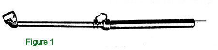
This tire gage is the brass stick about a foot long (Fig. 1) which we hinted last month is not receiving the proper care. As a matter of fact, you mention the driver’s tire gage and you’ll drew a sharp razzberry from many a driver and many a mechanic.
From Army Motors, Volume 3, page 317.
Not very long ago, the tire gage* was made part of the vehicle tool set. Today, every driver is entitled to one.
This tire gage is the brass stick about a foot long (Fig. 1) which we hinted last month is not receiving the proper care. As a matter of fact, you mention the driver’s tire gage and you’ll drew a sharp razzberry from many a driver and many a mechanic.
 But the fault is not with the tire gage. It’s a sturdily constructed and satisfactory instrument, and will stand up under the normal conditions of use in the field. It wasn’t intended, however, to be used as a supplementary hammer or as a crowbar for light work.
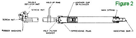
Take a look at what’s on the inside of the gage (Fig. 2) and you’ll see why. There’s the ‘foot’, the part of the gage you stick on the tire valve when checking tire pressure. Inside the foot is a double deflator unit. When you put the foot on the tire valve, the deflator pushes down the tire-valve core and allows the pressure of the air in the tire to rush into the stem of the gage. At the same time the deflator seats against the rubber seal on the other side of the foot to keep the air from rushing right out again. (The other side of the foot, you know, is to enable you to take care of the inside tires of dual-wheeled jobs.
But the fault is not with the tire gage. It’s a sturdily constructed and satisfactory instrument, and will stand up under the normal conditions of use in the field. It wasn’t intended, however, to be used as a supplementary hammer or as a crowbar for light work.
Take a look at what’s on the inside of the gage (Fig. 2) and you’ll see why. There’s the ‘foot’, the part of the gage you stick on the tire valve when checking tire pressure. Inside the foot is a double deflator unit. When you put the foot on the tire valve, the deflator pushes down the tire-valve core and allows the pressure of the air in the tire to rush into the stem of the gage. At the same time the deflator seats against the rubber seal on the other side of the foot to keep the air from rushing right out again. (The other side of the foot, you know, is to enable you to take care of the inside tires of dual-wheeled jobs.
 Stop right here and consider a couple of things. Applying the foot to the tire valve for instance. Now we don’t want to insult your intelligence: but if you don’t get the foot on square and tight, you won’t get an accurate reading. The air pressure squeezes out between the washer and the valve tip and the reading is lower than it should be. Another point: the things that wear out first in the gage, are the rubber washers in the foot. Poked at the sharp edges of the tire valve, they are cut and slowly worn away. These little rubber washers (together with the screw nuts) are available from your supply channels+ — don’t be afraid to requisition them. To replace the washers simply take out the screw nut in the foot, discard the old washers, press the new ones in squarely and replace the screw nut. You’ll need a big screwdriver to engage the slots on both sides of the hole.
The air that enters the foot rushes up the skinny part of the stem, squeezes past and is cleaned by a felt “filter washer,” whistles through a small passage in the “spreading plug”and strikes the “plunger.”
The plunger activates the e gaging mechanism. Its nose is inserted in the bottom end of the calibrated “indicating bar” and its shoulders push against the coiled “main spring.” The tension of this main spring and the air pressure striking the plunger decide how far out the calibrated indicating bar will be pushed. The indicating bar pops out the end of the gage and you have your reading.
(By the way, did you know you’re supposed to practice reading the indicating bar with your fingers until you’re able to read it in a blackout?)
To protect the guts of the gage from normal metal corrosion, the inside of the barrel containing the coil spring and indicator, is nickel plated, the indicating bar itself is nickel plated and the whole is lubricated.
And there you have the simple, non-mysterious mechanism of the tire gage. Nothing to fall apart or wear out easily.
Well, what will damage the gage?
As mentioned before, using the gage as a hammer just because you happen to have it in your hand, will dent the barrel. Any dent in the barrel prevents the plunger from riding smoothly — it may even stop it altogether – giving you erratic readings according to where the dent happens to be, and what the pressure of the particular tire being checked, happens to be.
Oil getting into the foot will attack and ruin the rubber seals.
Any water – especially salt water — entering into the mechanism will eventually cause corrosion and rust which will damage and otherwise interfere with the operation of the plunger. Dust and dirt will do the same. Dirt accumulating in the foot is responsible for clogging many gages.
The favorite trick of applying the gage foot to a valve that happens to be bent down to the wheel rim, and then prying the valve up to where it’s more easily reached, will beat up the washers.
You see just a lot of little foolishness that common sense will avoid.
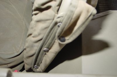
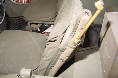
Taking the gage out of the tool box where it picks up dirt and gets bounced around by heavier tools is the first common sense move. Hang the gage in the cab, foot down. This will keep the indicating bar from working out and being damaged. To encourage you to hang them up, we hear that the later gages will be coming through with rings on them.
Every company has a master gage to cheek the driver’s gages by. The master gage is an expensive precision-built instrument boxed in a small, velvet-lined coffin. We suggest that a slight ritual take place every week or so in which each driver approaches the Master Gage with fear and trembling to have his tire gage checked.
Speaking of the master gage, two free factory recalibrations are contracted for with each of these gages. They should be exchanged for new gages at the supply depots. Unserviceable driver’s gages should also he exchanged for new ones. When the depot has about a hundred of the unserviceable gages, it ships them back to the factory for reworking.
Question: “Why not design the gages so they can be recalibrated in the field?”Answer: “It’s not too difficult to recalibrate the gages for one particular reading, but it takes a whole set of master gages and instruments to recalibrate them correctly for all pressure readings.”
Turning the whole matter of the tire gage over in our mind the other night while fondling a glass of stale beer, it seemed to us that here was a pretty good thing. Imagine a mass-produced instrument with a range of from 10 to 160 lbs. capable of checking every tire in the Army! Not bad!
If you don’t believe us, go get your own glass of beer and think it over. We’ll wait right here for your answer.
*The “Tool and Equipment List” says “gage”. The government style manual says “gauge.”
+Screw nuts Fed. Stock No. 5-0-615—18
Washers Fed. Stock No. 8-0-615—28
Stop right here and consider a couple of things. Applying the foot to the tire valve for instance. Now we don’t want to insult your intelligence: but if you don’t get the foot on square and tight, you won’t get an accurate reading. The air pressure squeezes out between the washer and the valve tip and the reading is lower than it should be. Another point: the things that wear out first in the gage, are the rubber washers in the foot. Poked at the sharp edges of the tire valve, they are cut and slowly worn away. These little rubber washers (together with the screw nuts) are available from your supply channels+ — don’t be afraid to requisition them. To replace the washers simply take out the screw nut in the foot, discard the old washers, press the new ones in squarely and replace the screw nut. You’ll need a big screwdriver to engage the slots on both sides of the hole.
The air that enters the foot rushes up the skinny part of the stem, squeezes past and is cleaned by a felt “filter washer,” whistles through a small passage in the “spreading plug”and strikes the “plunger.”
The plunger activates the e gaging mechanism. Its nose is inserted in the bottom end of the calibrated “indicating bar” and its shoulders push against the coiled “main spring.” The tension of this main spring and the air pressure striking the plunger decide how far out the calibrated indicating bar will be pushed. The indicating bar pops out the end of the gage and you have your reading.
(By the way, did you know you’re supposed to practice reading the indicating bar with your fingers until you’re able to read it in a blackout?)
To protect the guts of the gage from normal metal corrosion, the inside of the barrel containing the coil spring and indicator, is nickel plated, the indicating bar itself is nickel plated and the whole is lubricated.
And there you have the simple, non-mysterious mechanism of the tire gage. Nothing to fall apart or wear out easily.
Well, what will damage the gage?
As mentioned before, using the gage as a hammer just because you happen to have it in your hand, will dent the barrel. Any dent in the barrel prevents the plunger from riding smoothly — it may even stop it altogether – giving you erratic readings according to where the dent happens to be, and what the pressure of the particular tire being checked, happens to be.
Oil getting into the foot will attack and ruin the rubber seals.
Any water – especially salt water — entering into the mechanism will eventually cause corrosion and rust which will damage and otherwise interfere with the operation of the plunger. Dust and dirt will do the same. Dirt accumulating in the foot is responsible for clogging many gages.
The favorite trick of applying the gage foot to a valve that happens to be bent down to the wheel rim, and then prying the valve up to where it’s more easily reached, will beat up the washers.
You see just a lot of little foolishness that common sense will avoid.
Taking the gage out of the tool box where it picks up dirt and gets bounced around by heavier tools is the first common sense move. Hang the gage in the cab, foot down. This will keep the indicating bar from working out and being damaged. To encourage you to hang them up, we hear that the later gages will be coming through with rings on them.
Every company has a master gage to cheek the driver’s gages by. The master gage is an expensive precision-built instrument boxed in a small, velvet-lined coffin. We suggest that a slight ritual take place every week or so in which each driver approaches the Master Gage with fear and trembling to have his tire gage checked.
Speaking of the master gage, two free factory recalibrations are contracted for with each of these gages. They should be exchanged for new gages at the supply depots. Unserviceable driver’s gages should also he exchanged for new ones. When the depot has about a hundred of the unserviceable gages, it ships them back to the factory for reworking.
Question: “Why not design the gages so they can be recalibrated in the field?”Answer: “It’s not too difficult to recalibrate the gages for one particular reading, but it takes a whole set of master gages and instruments to recalibrate them correctly for all pressure readings.”
Turning the whole matter of the tire gage over in our mind the other night while fondling a glass of stale beer, it seemed to us that here was a pretty good thing. Imagine a mass-produced instrument with a range of from 10 to 160 lbs. capable of checking every tire in the Army! Not bad!
If you don’t believe us, go get your own glass of beer and think it over. We’ll wait right here for your answer.
*The “Tool and Equipment List” says “gage”. The government style manual says “gauge.”
+Screw nuts Fed. Stock No. 5-0-615—18
Washers Fed. Stock No. 8-0-615—28
Storing the Air Gage


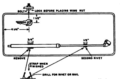 T/4 Benny Pilara, our shop foreman, is the pappy of the following: knock out the second rivet in each of the data plates on the glove-box door of the l/4-ton, make a spring clip for each and of the tire gage from the metal bands taken from any packing case and rivet them on the inside of the door. Paint the outline of the gage on the door, slip the gage into the clips and there is no excuse for the cry. “I’ve lost mytire gage.” And the spare key? Just drill a 3/16 bole in the glove-box door, insert a 3/16 x 3/4 stove bolt, tighten the nut, put the key on the belt and fasten it in place with a wing nut taken from an ammunition box. The same idea may be used en any vehicle except the amphibian which has no glove compartment.
S. J. Freeman
M/Sgt. 307th Inf.
T/4 Benny Pilara, our shop foreman, is the pappy of the following: knock out the second rivet in each of the data plates on the glove-box door of the l/4-ton, make a spring clip for each and of the tire gage from the metal bands taken from any packing case and rivet them on the inside of the door. Paint the outline of the gage on the door, slip the gage into the clips and there is no excuse for the cry. “I’ve lost mytire gage.” And the spare key? Just drill a 3/16 bole in the glove-box door, insert a 3/16 x 3/4 stove bolt, tighten the nut, put the key on the belt and fasten it in place with a wing nut taken from an ammunition box. The same idea may be used en any vehicle except the amphibian which has no glove compartment.
S. J. Freeman
M/Sgt. 307th Inf.