 I was just sitting here thinking about the constant velocity universal joint and how important it is to the function and operation of the WW2 jeep and any four wheel drive vehicle.
A constant velocity universal joint transmits a smooth rotation from a drivlng shaft to a driyen shaft at any working angle without the usual speeding up and slowing down action that is customary in a shaft driven by a universal Joint of the simple, pin, yoke, or spider type.
 Simple universal joints are unsuitable for front wheel drives because the variable speeds of the driven shaft cause a severe whipping action in the steering gear when making a turn.
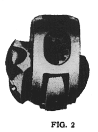
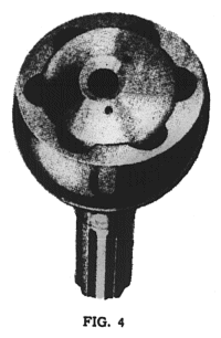
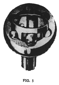
Constant velocity universal joint?s are of either the disk or the bell type. (See illustrations) Disk joints, attached to a companion flange of six fitted bolts and equipped with telescoping metal seals, are capable of a fifteen degree deflection and can be used with sliding or permanently fitted splined drive shafts.
Bell joints, which permit a thirty-seven degree deflection, have a somewhat smaller overall diameter. They have a driven shank, which is forged integrally with the bell housing and splined drive shaft.These limited angles of deflection are the reason for using stop bolts on front driving axles. They are usually set at thirty degrees and never over thirty-seven degrees to prevent excessive cramping angles when steering a vehicle. Strained angles of deflectidn will cause bell fractures and other failures within the joint.
Constant velocity joints are particularly useful in all types of motor vehicles, from, the lightest passenger car to the heaviest truck. With the increased use of independently sprung wheels, front drive steering axles, and. four, six and other multiple drives, the need for a constant velocity and, strong high angle universal joint is becoming more, urgent every day. They have a wide range of uses in machine tools, industrial machinery, power winches, etc.
General instructions pertaining to these front axle steering drive ends are published in “Motor Transport Technical Service Bulletins No. Pl and No. P2”, Office of The Quartermaster General.


